Skip to content
Features
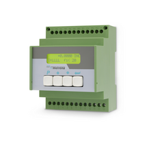
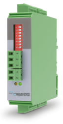
6-wire connection for one strain gauge full bridge sensor
4 control inputs [HTL/PNP]
1 analog output ±10 V, 0/4 ... 20 mA, 16 bit
4 control outputs for signalling different operation states
Power supply 18 ... 30 VDC
Functions for scaling and linking the sensor signals (e.g. A+B, A-B, ...)
Adjustable bridge voltage per sensor from 3 VDC ... 10 VDC
Sensitivity of the sensor inputs 1 ... 10 mV
Transmission of the sensor data via RS485
Programming via USB and the user interface OS (freeware)
Protection class IP20
Compact housing for mounting on 35 mm top-hat rail (according to EN 60715)
Features
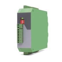
6-wire connection for two independent strain gauge full bridge sensors
4 control inputs [HTL/PNP]
2 independent analog outputs ±10 V, 0/4 ... 20 mA, 16 bit
4 control outputs for signalling different operation states
Power supply 18 ... 30 VDC
Functions for scaling and linking the sensor signals (e.g. A+B, A-B, ...)
Adjustable bridge voltage per sensor from 3 VDC ... 10 VDC
Sensitivity of the sensor inputs 1 ... 10 mV
Transmission of the sensor data via RS485
Programming via USB and the user interface OS (freeware)
Protection class IP20
Compact housing for mounting on 35 mm top-hat rail (according to EN 60715)
Features
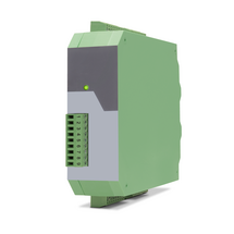
Input frequency up to 500 kHz with HTL or 1 MHz with RS422 / TTL
4 pulse outputs, formats correspond to those of the input signals, but with individual assignment of the output level for each output
BUS interface for quick and easy connection of the modules
Power supply 10 ... 30 VDC
Signal delay time 160 ns
Input level at RS422 / TTL (differential voltage > 0.5 V),
Input level at HTL differential (differential voltage > 2 V),
Input level at HTL asymmetric low: 0 ... 6 V, high: 8 ... 40 V
Input level at TTL (asymmetrical): LOW < 0.8 V, HIGH >2.0 V
Compact housing for mounting on 35 mm top hat rail (according to EN 60715)
Dimensions W x H x D = 34 x 118 x 140 mm (1,34 x 4,65 x 5,51")
Features
Input frequency up to 500 kHz with HTL or 1 MHz with RS422 / TTL
8 pulse outputs, formats correspond to those of the input signals, but with individual assignment of the output level for each output
BUS interface for quick and easy connection of the modules
Power supply 10 ... 30 VDC
Signal delay time 160 ns
Input level at RS422 / TTL (differential voltage > 0.5 V),
Input level at HTL differential (differential voltage > 2 V),
Input level at HTL asymmetric low: 0 ... 6 V, high: 8 ... 40 V
Input level at TTL (asymmetrical): LOW < 0.8 V, HIGH >2.0 V
Compact housing for mounting on 35 mm top hat rail (according to EN 60715)
Dimensions W x H x D = 54 x 118 x 140 mm (2,13 x 4,65 x 5,51")
Features
Input frequency up to 500 kHz with HTL or 1 MHz with RS422 / TTL
4 pulse outputs, formats correspond to those of the input signals, but with individual assignment of the output level for each output
BUS interface for quick and easy connection of the modules
Power supply 10 ... 30 VDC
Signal delay time 160 ns
Input level at RS422 / TTL (differential voltage > 0.5 V),
Input level at HTL differential (differential voltage > 2 V),
Input level at HTL asymmetric low: 0 ... 6 V, high: 8 ... 40 V
Input level at TTL (asymmetrical): LOW < 0.8 V, HIGH >2.0 V
Compact housing for mounting on 35 mm top hat rail (according to EN 60715)
Dimensions W x H x D = 34 x 118 x 140 mm (1,34 x 4,65 x 5,51")
Features
Input frequency up to 500 kHz with HTL or 1 MHz with RS422 / TTL
8 pulse outputs, formats correspond to those of the input signals, but with individual assignment of the output level for each output
BUS interface for quick and easy connection of the modules
Power supply 10 ... 30 VDC
Signal delay time 160 ns
Input level at RS422 / TTL (differential voltage > 0.5 V),
Input level at HTL differential (differential voltage > 2 V),
Input level at HTL asymmetric low: 0 ... 6 V, high: 8 ... 40 V
Input level at TTL (asymmetrical): LOW < 0.8 V, HIGH >2.0 V
Compact housing for mounting on 35 mm top hat rail (according to EN 60715)
Dimensions W x H x D = 54 x 118 x 140 mm (2,13 x 4,65 x 5,51")
Features
Pulse input with format A, B, Z [HTL single-ended, TTL single-ended] or A, /A, B, /B, Z, /Z [RS422, HTL differential]
4 control inputs for HTL, PNP signals [10 ... 30 VDC]
Input and output frequency up to 1 MHz
3 incremental outputs with format A, /A, B, /B, Z, /Z, Push-Pull, [8 … 29 VDC]
Power supply 9 ... 30 VDC
Snap-on housing for top-hat rail (acc. EN 60715)
Multiplier/divisor adjustable as quotient F1 / F2
Multiplication/division without cumulative residual errors
Additional functions such as jog, trim, offset and reference
Features
Pulse input with format A, B, 90° [HTL] or A, /A, B, /B, Z, /Z [RS422]
4 control inputs for PNP signals [10 ... 30 VDC]
Input and output frequency up to 1 MHz
Pulse output with format A, /A, B, /B, Z, /Z and
push-pull characteristic, [5 ... 30 VDC]
Power supply 11 ... 30 VDC
Snap-on housing for top-hat rail (according to EN 60715)
LCD backlighted
Setup via keys, RS232
The device multiplies an incoming frequency by a proportional factor F1 and a reciprocal factor F2. The two factors F1 and F2 are adjustable in the range of 0.0005 to 9.9999
All operation modes provide error-free frequency conversion, with full consideration of the A / B phase and direction of the quadrature signals, therefore no cumulative errors, even with continuous changes of directions and vibrations
Zero pulse generator: the frequency multiplier generates at the output an index signal with an adjustable pulse interval, which can be synchronized as needed with the zero pulse at the input
Features
Frequency inputs A, B [HTL], A, / A, B, / B [RS422, HTL]
3 control inputs (hold) for PNP signals [10 ... 30 VDC]
SSI input in the format DATA +, DATA-, CLOCK +, CLOCK- up to 32 bits
Start-stop interface for absolute transducers and magnetostrictive sensors
Input frequency up to 1 MHz
25-bit parallel output push-pull in BCD, binary or Gray code format
Power supply 18 ... 30 VDC
Compact housing for mounting on 35 mm top-hat rail (according to EN 60715)
Features
Pulse inputs A, B [HTL], A, /A, B, /B [RS422, HTL]
Input frequency up to 1 MHz [RS422], 200 kHz [HTL]
Analog output ±10 V or 0/4 ... 20 mA, 16 Bit
Power supply 18 ... 30 VDC
Snap-on housing for top-hat rail (according to EN 60715)
Setup via operator software OS6.0
Serial RS232- / RS485 interface
SSI input DATA+, DATA-, CLOCK+, CLOCK- [RS422], 32 Bit
Start-stop interface for absolute transducers and magnetostrictive sensors
USB interface and RS232/RS485 interface for configuration and serial readout
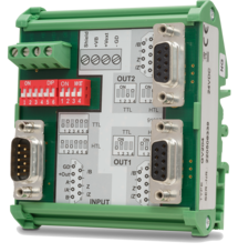
Features
Control input with format [HTL]
2 SSI inputs with format [RS422]
Cutt-off frequency 100 kHz ... 1 MHz
2 encoder inputs, short-circuit-proof
1 SSI output with format [RS422]
Power supply 12 ... 30 V DC
Current consumption (unloaded) 50 mA
Encoder supply 2 x 125mA (Vin – 2 V) short-circuit-proof
Delay / Output / Input100 ns
Operation temperature : 0 ... 45 °C (32 ... 113 °F)
SSI pause time min. 25 ns
Switching time is synchronized automatically with the next SSI break
Cascadable for more SSI encoders
All connections via pluggable screw terminal block
Snap-on housing for top-hat rail (according to EN 60715)
LEDs for indication of the input pulses
Dimension W x H x D = 22,5 x 121 x 112 mm (8.86 x 47.64 x 44.09'')
Plastic housing incl. plug
Features
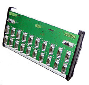
2 x 6 control outputs für HTL / PNP signals
Pulse inputs with format A, /A, B, /B, Z, /Z [RS422]
Input frequency up to 1 MHz
2 encoder outputs, short-circuit-proof [TTL / RS422]
Power supply 12 ... 30 VDC
Current consumption (unloaded) 30 mA
Encoder supply 5 ... 35 VDC (extern connect to +VAUX)
Operation temperature: 0 ... 60 °C (32 ... 140°F)
Latency time < 250ns
Channel switching < 1 ms
Open plastic housing for top-hat rail (according to EN 60715)
LEDs for indication of the input pulses
Features
1 pulse input with format A, B, Z [HTL] or A, /A, B, /B, Z, /Z [RS422]
Input frequency up to 500 kHz with HTL or 1 MHz with RS422 / TTL
2 pulse outputs, formats correspond to those of the input signals, but with individual assignment of the output level for each output
BUS interface for quick and easy expansion of the number of outputs
Power supply 10 ... 30 VDC
Signal delay time 160 ns
Input level at RS422 / TTL (differential voltage > 0.5 V),
Input level at HTL differential (differential voltage > 2 V),
Input level at HTL asymmetric low: 0 ... 6 V, high: 8 ... 40 V
Input level at TTL (asymmetrical): LOW < 0.8 V, HIGH >2.0 V
Compact housing for mounting on 35 mm top hat rail (according to EN 60715)
Dimensions W x H x D = 34 x 118 x 140 mm (1,34 x 4,65 x 5,51")
Features
1 pulse input with format A, B, Z [HTL] or A, /A, B, /B, Z, /Z [RS422]
Input frequency up to 500 kHz with HTL or 1 MHz with RS422 / TTL
4 pulse outputs, formats correspond to those of the input signals, but with individual assignment of the output level for each output
BUS interface for quick and easy expansion of the number of outputs
Power supply 10 ... 30 VDC
Signal delay time 160 ns
Input level at RS422 / TTL (differential voltage > 0.5 V),
Input level at HTL differential (differential voltage > 2 V),
Input level at HTL asymmetric low: 0 ... 6 V, high: 8 ... 40 V
Input level at TTL (asymmetrical): LOW < 0.8 V, HIGH >2.0 V
Compact housing for mounting on 35 mm top hat rail (according to EN 60715)
Dimensions W x H x D = 34 x 118 x 140 mm (1,34 x 4,65 x 5,51")
Features
1 pulse input with format A, B, Z [HTL] or A, /A, B, /B, Z, /Z [RS422]
Input frequency up to 500 kHz with HTL or 1 MHz with RS422 / TTL
8 pulse outputs, formats correspond to those of the input signals, but with individual assignment of the output level for each output
BUS interface for quick and easy expansion of the number of outputs
Power supply 10 ... 30 VDC
Signal delay time 160 ns
Input level at RS422 / TTL (differential voltage > 0.5 V),
Input level at HTL differential (differential voltage > 2 V),
Input level at HTL asymmetric low: 0 ... 6 V, high: 8 ... 40 V
Input level at TTL (asymmetrical): LOW < 0.8 V, HIGH >2.0 V
Compact housing for mounting on 35 mm top hat rail (according to EN 60715)
Dimensions W x H x D = 54 x 118 x 140 mm (2,13 x 4,65 x 5,51")
Features
1 encoder input programmable with format A, /A, B, /B, Z, /Z [TTL / RS422] or optionally A, B, Z [HTL]
Input frequency 750 kHz [TTL] or 300 kHz [HTL]
2 pulse outputs with format A, /A, B, /B, Z, /Z with individual adjustable output levels 5 V [TTL] or 10 ... 30 V [HTL]
Power supply optionally 5 VDC or 10 ... 30 VDC
Auxiliary voltage +5 V for encoder supply 10 ... 30 VDC
Features
2 pulse inputs with format A, B, Z [HTL] or A, /A, B, /B, Z, /Z [RS422]
Input frequency up to 250 kHz for asymmetrical and up to 1 MHz for symmetric signals
2 control inputs for HTL / PNP signals [10 ... 30 VDC]
2 output channels with format A, B, Z [HTL] or A, /A, B, /B, Z, /Z [RS422], each output adjustable separately
Power supply 12 ... 30 VDC
Snap-on housing for top-hat rail (according to EN 60715)
Features
1 pulse input with format A, B, Z [HTL] or A, /A, B, /B, Z, /Z [RS422]
Input frequency up to 500 kHz with HTL or 1 MHz with RS422 / TTL
4 pulse outputs, formats correspond to those of the input signals, but with individual assignment of the output level for each output
BUS interface for quick and easy expansion of the number of outputs
Power supply 10 ... 30 VDC
Signal delay time 160 ns
Input level at RS422 / TTL (differential voltage > 0.5 V),
Input level at HTL differential (differential voltage > 2 V),
Input level at HTL asymmetric low: 0 ... 6 V, high: 8 ... 40 V
Input level at TTL (asymmetrical): LOW < 0.8 V, HIGH >2.0 V
Compact housing for mounting on 35 mm top hat rail (according to EN 60715)
Dimensions W x H x D = 34 x 118 x 140 mm (1,34 x 4,65 x 5,51")
Features
1 pulse input with format A, B, Z [HTL] or A, /A, B, /B, Z, /Z [RS422]
Input frequency up to 500 kHz with HTL or 1 MHz with RS422 / TTL
8 pulse outputs, formats correspond to those of the input signals, but with individual assignment of the output level for each output
BUS interface for quick and easy expansion of the number of outputs
Power supply 10 ... 30 VDC
Signal delay time 160 ns
Input level at RS422 / TTL (differential voltage > 0.5 V),
Input level at HTL differential (differential voltage > 2 V),
Input level at HTL asymmetric low: 0 ... 6 V, high: 8 ... 40 V
Input level at TTL (asymmetrical): LOW < 0.8 V, HIGH >2.0 V
Compact housing for mounting on 35 mm top hat rail (according to EN 60715)
Dimensions W x H x D = 54 x 118 x 140 mm (2,13 x 4,65 x 5,51")
Features
1 pulse input with format A, B, Z [HTL] or A, /A, B, /B, Z, /Z [RS422]
Input frequency up to 500 kHz with HTL or 1 MHz with RS422 / TTL
8 pulse outputs, formats correspond to those of the input signals, but with individual assignment of the output level for each output
BUS interface for quick and easy expansion of the number of outputs
Power supply 10 ... 30 VDC
Signal delay time 160 ns
Input level at RS422 / TTL (differential voltage > 0.5 V),
Input level at HTL differential (differential voltage > 2 V),
Input level at HTL asymmetric low: 0 ... 6 V, high: 8 ... 40 V
Input level at TTL (asymmetrical): LOW < 0.8 V, HIGH >2.0 V
Compact housing for mounting on 35 mm top hat rail (according to EN 60715)
Dimensions W x H x D = 54 x 118 x 140 mm (2,13 x 4,65 x 5,51")
Features
4 analog inputs for ±10 V or 0/4 ... 20 mA (2x current / 2x voltage)
optionally 3 control inputs for PNP signals [10 ... 30 VDC]
IO link interface
Power supply 12 ... 30 VDC
Compact housing for mounting on 35 mm DIN rail (according to EN 60715)
Features
1 Strain gauge input
3 VDC and 10 VDC bridge voltage per sensor connection
1 … 10 mV sensitivity
optionally 3 control inputs for PNP signals [10 ... 30 VDC]
IO link interface
Power supply 12 ... 30 VDC
Compact housing for mounting on 35 mm DIN rail (according to EN 60715)
Features
1 incremental input (A, /A, B, /B)
for HTL/TTL/RS422 for NPN/PNP/NAMUR encoders and sensors
optionally 3 control inputs for PNP signals [10 ... 30 VDC]
IO link interface
Power supply 12 ... 30 VDC
Compact housing for mounting on 35 mm DIN rail (according to EN 60715)
Features
1 SSI input (10 … 32 bit)
for single-turn and multiturn encoders
optionally 3 control inputs for PNP signals [10 ... 30 VDC]
IO link interface
Power supply 12 ... 30 VDC
Compact housing for mounting on 35 mm DIN rail (according to EN 60715)
Page load link